SD-WAN
集团多分支节点智能化组网
发布时间:2021-10-09 13:44:39 作者:颜采蘋阅读:0
在EVPN数据中心互联场景中,为了提高ED的可靠性,避免单点故障,在数据中心的边缘可以部署两台ED设备与其他数据中心互联。这两台ED设备使用相同的虚拟IP地址,虚拟成一台ED设备,采用虚拟IP地址与VTEP、远端ED建立隧道,以实现冗余保护和负载分担。两台ED使用不同的地址作为BGP对等体地址,分别与VTEP、远端ED建立BGP EVPN邻居。利用Underlay网络的等价路由机制,VTEP、远端ED可以将发往ED虚拟IP地址的流量同时发送到两台ED,从而实现冗余备份和负载分担。
在连接不同数据中心ED的DCI网络侧,两台ED均通过Underlay网络与对端数据中心ED建立连接。当一台ED的DCI侧Underlay网络出现故障时,数据中心内部网络无法感知该故障,仍通过该ED转发数据中心间的流量。通过配置Monitor Link组,将DCI侧的物理接口与ED设备的LoopBack接口(用于建立BGP EVPN邻居的接口)关联,可以确保其中一台ED设备的DCI侧Underlay网络断开时,将该ED的LoopBack接口链路状态置为down,使流量通过另外一台ED设备转发。(来自H3C)
组网需求
R1为数据中心1的分布式网关,R7为数据中心2的分布式网关,R2作为路由反射器,R3和R4为数据中心1的双ED设备,R6为数据中心2的ED设备,R5为连接两个数据中心ED设备的DCI网络设备。通过EVPN数据中心互连实现数据中心1和数据中心2的三层互通。
组网图
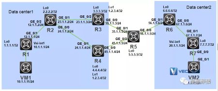
配置步骤
1.配置IP地址和单播路由协议
在VM 1上指定网关地址为10.1.1.1;在VM 2上指定网关地址为20.1.1.1。
配置各接口的IP地址和子网掩码;在IP核心网络内配置OSPF协议,确保路由器之间路由可达。具体配置如下:
R1
system-view
interface LoopBack0
ip address 1.1.1.1 255.255.255.255
interface GigabitEthernet0/1
ip address 12.1.1.1 255.255.255.0
ospf 1 router-id 1.1.1.1
area 0.0.0.0
network 1.1.1.1 0.0.0.0
network 12.1.1.0 0.0.0.255
R2
system-view
interface LoopBack0
ip address 2.2.2.2 255.255.255.255
interface GigabitEthernet0/2
ip address 12.1.1.2 255.255.255.0
interface GigabitEthernet0/1
ip address 23.1.1.2 255.255.255.0
interface GigabitEthernet0/0
ip address 24.1.1.2 255.255.255.0
ospf 1 router-id 2.2.2.2
area 0.0.0.0
network 2.2.2.2 0.0.0.0
network 12.1.1.0 0.0.0.255
network 23.1.1.0 0.0.0.255
network 24.1.1.0 0.0.0.255
R3
system-view
interface LoopBack0
ip address 3.3.3.3 255.255.255.255
interface LoopBack1
ip address 1.2.3.4 255.255.255.255
interface GigabitEthernet0/2
ip address 23.1.1.3 255.255.255.0
interface GigabitEthernet0/0
ip address 35.1.1.3 255.255.255.0
ospf 1 router-id 3.3.3.3
area 0.0.0.0
network 3.3.3.3 0.0.0.0
network 1.2.3.4 0.0.0.0
network 23.1.1.0 0.0.0.255
network 35.1.1.0 0.0.0.255
R4
system-view
interface LoopBack0
ip address 4.4.4.4 255.255.255.255
interface LoopBack1
ip address 1.2.3.4 255.255.255.255
interface GigabitEthernet0/1
ip address 24.1.1.4 255.255.255.0
interface GigabitEthernet0/0
ip address 45.1.1.4 255.255.255.0
ospf 1 router-id 4.4.4.4
area 0.0.0.0
network 4.4.4.4 0.0.0.0
network 1.2.3.4 0.0.0.0
network 24.1.1.0 0.0.0.255
network 45.1.1.0 0.0.0.255
R5
system-view
interface LoopBack0
ip address 5.5.5.5 255.255.255.255
interface GigabitEthernet0/2
ip address 45.1.1.5 255.255.255.0
interface GigabitEthernet0/1
ip address 35.1.1.5 255.255.255.0
interface GigabitEthernet0/0
ip address 56.1.1.5 255.255.255.0
ospf 1 router-id 5.5.5.5
area 0.0.0.0
network 5.5.5.5 0.0.0.0
network 45.1.1.0 0.0.0.255
network 35.1.1.0 0.0.0.255
network 56.1.1.0 0.0.0.255
R6
system-view
interface LoopBack0
ip address 6.6.6.6 255.255.255.255
interface GigabitEthernet0/1
ip address 56.1.1.6 255.255.255.0
interface GigabitEthernet0/0
ip address 67.1.1.6 255.255.255.0
ospf 1 router-id 6.6.6.6
area 0.0.0.0
network 6.6.6.6 0.0.0.0
network 67.1.1.0 0.0.0.255
network 56.1.1.0 0.0.0.255
R7
system-view
interface LoopBack0
ip address 7.7.7.7 255.255.255.255
interface GigabitEthernet0/1
ip address 67.1.1.7 255.255.255.0
ospf 1 router-id 7.7.7.7
area 0.0.0.0
network 7.7.7.7 0.0.0.0
network 67.1.1.0 0.0.0.255
验证R1路由:
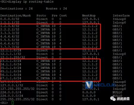
2.配置EVPN和VXLAN
R1
system-view
l2vpn enable
vxlan tunnel mac-learning disable
vxlan tunnel arp-learning disable
vsi vpna
vxlan 10
evpn encapsulation vxlan
route-distinguisher auto
vpn-target auto
bgp 100
peer 2.2.2.2 as-number 100
peer 2.2.2.2 connect-interface loopback 0
address-family l2vpn evpn
peer 2.2.2.2 enable
interface gigabitethernet 0/0
xconnect vsi vpna
ip vpn-instance vpn1
route-distinguisher 1:1
address-family ipv4
vpn-target 2:2
address-family evpn
vpn-target 1:1
interface vsi-interface 1
ip binding vpn-instance vpn1
ip address 10.1.1.1 255.255.255.0
mac-address 1-1-1
distributed-gateway local
interface vsi-interface 2
ip binding vpn-instance vpn1
l3-vni 1000
vsi vpna
gateway vsi-interface 1
R2
# 配置BGP路由反射。
bgp 100
group evpn internal
peer evpn connect-interface loopback 0
peer 1.1.1.1 group evpn
peer 3.3.3.3 group evpn
peer 4.4.4.4 group evpn
address-family l2vpn evpn
undo policy vpn-target
peer evpn enable
peer evpn reflect-client
quit
R3
system-view
l2vpn enable
vxlan tunnel mac-learning disable
vxlan tunnel arp-learning disable
interface gigabitethernet 0/0
dci enable
bgp 100
peer 6.6.6.6 as-number 200
peer 6.6.6.6 connect-interface loopback 0
peer 6.6.6.6 ebgp-max-hop 64
peer 2.2.2.2 as-number 100
peer 2.2.2.2 connect-interface loopback 0
address-family l2vpn evpn
peer 6.6.6.6 enable
peer 6.6.6.6 router-mac-local
peer 2.2.2.2 enable
peer 2.2.2.2 next-hop-local
quit
quit
ip vpn-instance vpn1
route-distinguisher 1:2
address-family ipv4
vpn-target 2:2
address-family evpn
vpn-target 1:1
interface vsi-interface 2
ip binding vpn-instance vpn1
l3-vni 1000
mac-address 1-2-3
# 配置ED的虚拟IP地址为接口LoopBack1的IP地址1.2.3.4,并配置通过OSPF发布该地址。(该步骤在前面已经配置)evpn edge group 1.2.3.4# 创建Monitor Link组,将与R5相连的物理接口、LoopBack0接口加入到Monitor Link组,设置Monitor Link组下行接口的回切延时为90秒。(模拟器路由器不支持)undo monitor-link disablemonitor-link group 1
port gigabitethernet 0/0 uplink
port loopback 0 downlink
downlink up-delay 90
R4(与R3相同)
system-view
l2vpn enable
vxlan tunnel mac-learning disable
vxlan tunnel arp-learning disable
interface gigabitethernet 0/0
dci enable
bgp 100
peer 6.6.6.6 as-number 200
peer 6.6.6.6 connect-interface loopback 0
peer 6.6.6.6 ebgp-max-hop 64
peer 2.2.2.2 as-number 100
peer 2.2.2.2 connect-interface loopback 0
address-family l2vpn evpn
peer 6.6.6.6 enable
peer 6.6.6.6 router-mac-local
peer 2.2.2.2 enable
peer 2.2.2.2 next-hop-local
quit
quit
ip vpn-instance vpn1
route-distinguisher 1:2
address-family ipv4
vpn-target 2:2
address-family evpn
vpn-target 1:1
interface vsi-interface 2
ip binding vpn-instance vpn1
l3-vni 1000
mac-address 1-2-3
# 配置ED的虚拟IP地址为接口LoopBack1的IP地址1.2.3.4,并配置通过OSPF发布该地址。(该步骤在前面已经配置)evpn edge group 1.2.3.4# 创建Monitor Link组,将与R5相连的物理接口、LoopBack0接口加入到Monitor Link组,设置Monitor Link组下行接口的回切延时为90秒。(模拟器路由器不支持)undo monitor-link disablemonitor-link group 1
port gigabitethernet 0/0 uplink
port loopback 0 downlink
downlink up-delay 90
R6
system-view
l2vpn enable
vxlan tunnel mac-learning disable
vxlan tunnel arp-learning disable
interface gigabitethernet 0/1
dci enable
bgp 200
peer 3.3.3.3 as-number 100
peer 3.3.3.3 connect-interface loopback 0
peer 3.3.3.3 ebgp-max-hop 64
peer 4.4.4.4 as-number 100
peer 4.4.4.4 connect-interface loopback 0
peer 4.4.4.4 ebgp-max-hop 64
peer 7.7.7.7 as-number 200
peer 7.7.7.7 connect-interface loopback 0
address-family l2vpn evpn
peer 3.3.3.3 enable
peer 3.3.3.3 router-mac-local
peer 4.4.4.4 enable
peer 4.4.4.4 router-mac-local
peer 7.7.7.7 enable
peer 7.7.7.7 next-hop-local
quit
quit
ip vpn-instance vpn1
route-distinguisher 1:4
address-family ipv4
vpn-target 2:2
address-family evpn
vpn-target 1:1
interface vsi-interface 2
ip binding vpn-instance vpn1
l3-vni 1000
R7
system-view
l2vpn enable
vxlan tunnel mac-learning disable
vxlan tunnel arp-learning disable
vsi vpnb
vxlan 20
evpn encapsulation vxlan
route-distinguisher auto
vpn-target auto
bgp 200
peer 6.6.6.6 as-number 200
peer 6.6.6.6 connect-interface loopback 0
address-family l2vpn evpn
peer 6.6.6.6 enable
interface gigabitethernet 0/0
xconnect vsi vpnb
ip vpn-instance vpn1
route-distinguisher 1:4
address-family ipv4
vpn-target 2:2
address-family evpn
vpn-target 1:1
interface vsi-interface 1
ip binding vpn-instance vpn1
ip address 20.1.1.1 255.255.255.0
mac-address 2-2-2
distributed-gateway local
interface vsi-interface 2
ip binding vpn-instance vpn1
l3-vni 1000
vsi vpnb
gateway vsi-interface 1
验证配置
1.验证R1(下文以R1为例,R7验证方法与此类似)
查看EVPN通过BGP自动发现的邻居信息,可以看到EVPN通过MAC/IP发布路由或IP前缀路由发现邻居ED设备(R3和R4组成的虚拟ED),并与其建立VXLAN隧道。

查看R1上的Tunnel接口信息,可以看到VXLAN模式Tunnel接口处于up状态。
<R1>display interface tunnel
Tunnel0
Current state: UP
Line protocol state: UP
Description: Tunnel0 Interface
Bandwidth: 64 kbps
Maximum transmission unit: 1464
Internet protocol processing: Disabled
Output queue - Urgent queuing: Size/Length/Discards 0/1024/0Output queue - Protocol queuing: Size/Length/Discards 0/500/0Output queue - FIFO queuing: Size/Length/Discards 0/75/0Last clearing of counters: NeverTunnel source 1.1.1.1, destination 1.2.3.4
Tunnel protocol/transport UDP_VXLAN/IP
Last 300 seconds input rate: 0 bytes/sec, 0 bits/sec, 0 packets/secLast 300 seconds output rate: 0 bytes/sec, 0 bits/sec, 0 packets/secInput: 11 packets, 850 bytes, 0 dropsOutput: 11 packets, 910 bytes, 0 drops
查看R1上的VSI信息,可以看到VSI内创建的VXLAN,以及关联的VXLAN隧道等信息。
<R1>dis l2vpn vsi verbose
VSI Name: Auto_L3VNI1000_2
VSI Index : 1
VSI State : Down
MTU : 1500
Bandwidth : -
Broadcast Restrain : -
Multicast Restrain : -
Unknown Unicast Restrain: -
MAC Learning : Enabled
MAC Table Limit : -
MAC Learning rate : -
Drop Unknown : -
PW Redundancy : Slave
Service Class : -
Flooding : Enabled
Gateway Interface : VSI-interface 2
VXLAN ID : 1000
VSI Name: vpna
VSI Index : 0
VSI State : Up
MTU : 1500
Bandwidth : -
Broadcast Restrain : -
Multicast Restrain : -
Unknown Unicast Restrain: -
MAC Learning : Enabled
MAC Table Limit : -
MAC Learning rate : -
Drop Unknown : -
PW Redundancy : Slave
Service Class : -
Flooding : Enabled
Gateway Interface : VSI-interface 1
VXLAN ID : 10
ACs:
AC Link ID StateGE0/0 0 Up<R1>
查看VPN实例vpn1的ARP表项和IP路由表项,可以看到已经学习到虚拟机的ARP和IP路由信息。

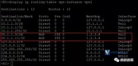
可以看到,学习VM2的ARP路由信息时,下一跳为1.2.3.4:
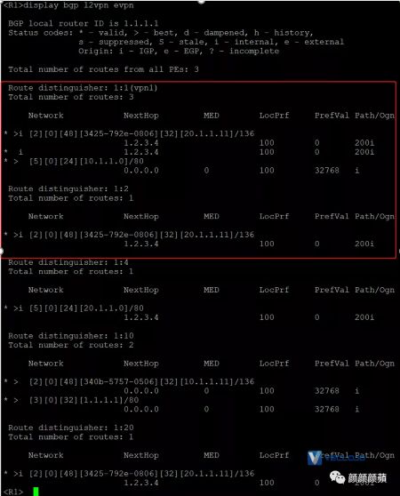
2.验证ED设备R3(下文以R3为例,R4验证方法与此类似)查看EVPN通过BGP自动发现的邻居信息,可以看到EVPN通过MAC/IP发布路由或IP前缀路由发现邻居R1和R6,并分别与其建立VXLAN隧道、VXLAN-DCI隧道。

查看R2上的Tunnel接口信息,可以看到VXLAN模式和VXLAN-DCI模式的Tunnel接口处于up状态。
<R3> display interface Tunnel
Tunnel0
Current state: UP
Line protocol state: UP
Description: Tunnel0 Interface
Bandwidth: 64 kbps
Maximum transmission unit: 1464
Internet protocol processing: Disabled
Output queue - Urgent queuing: Size/Length/Discards 0/1024/0Output queue - Protocol queuing: Size/Length/Discards 0/500/0Output queue - FIFO queuing: Size/Length/Discards 0/75/0Last clearing of counters: NeverTunnel source 1.2.3.4, destination 1.1.1.1
Tunnel protocol/transport UDP_VXLAN/IP
Last 300 seconds input rate: 0 bytes/sec, 0 bits/sec, 0 packets/secLast 300 seconds output rate: 0 bytes/sec, 0 bits/sec, 0 packets/secInput: 0 packets, 0 bytes, 0 dropsOutput: 0 packets, 0 bytes, 0 drops
Tunnel1
Current state: UP
Line protocol state: UP
Description: Tunnel1 Interface
Bandwidth: 64 kbps
Maximum transmission unit: 1464
Internet protocol processing: Disabled
Output queue - Urgent queuing: Size/Length/Discards 0/1024/0Output queue - Protocol queuing: Size/Length/Discards 0/500/0Output queue - FIFO queuing: Size/Length/Discards 0/75/0Last clearing of counters: NeverTunnel source 1.2.3.4, destination 6.6.6.6
Tunnel protocol/transport UDP_VXLAN_DCI/IP
Last 300 seconds input rate: 0 bytes/sec, 0 bits/sec, 0 packets/secLast 300 seconds output rate: 0 bytes/sec, 0 bits/sec, 0 packets/secInput: 0 packets, 0 bytes, 0 dropsOutput: 0 packets, 0 bytes, 0 drops
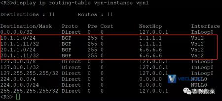
查看VPN实例vpn1的ARP表项和IP路由表项,可以看到已经学习到ARP和IP路由信息。

3.验证主机
虚拟机VM 1、VM 2之间可以互访:
<VM1>ping 20.1.1.11
Ping 20.1.1.11 (20.1.1.11): 56 data bytes, press CTRL+C to break56 bytes from 20.1.1.11: icmp_seq=0 ttl=251 time=3.000 ms56 bytes from 20.1.1.11: icmp_seq=1 ttl=251 time=2.000 ms56 bytes from 20.1.1.11: icmp_seq=2 ttl=251 time=2.000 ms56 bytes from 20.1.1.11: icmp_seq=3 ttl=251 time=3.000 ms56 bytes from 20.1.1.11: icmp_seq=4 ttl=251 time=2.000 ms--- Ping statistics for 20.1.1.11 ---5 packet(s) transmitted, 5 packet(s) received, 0.0% packet lossround-trip min/avg/max/std-dev = 2.000/2.400/3.000/0.490 ms<VM1>%Sep 7 22:18:59:453 2021 VM1 PING/6/PING_STATISTICS: Ping statistics for 20.1.1.11: 5 packet(s) transmitted, 5 packet(s) received, 0.0% packet loss, round-trip min/avg/max/std-dev = 2.000/2.400/3.000/0.490 ms.
<VM2>ping 10.1.1.11
Ping 10.1.1.11 (10.1.1.11): 56 data bytes, press CTRL+C to break56 bytes from 10.1.1.11: icmp_seq=0 ttl=251 time=3.000 ms56 bytes from 10.1.1.11: icmp_seq=1 ttl=251 time=3.000 ms56 bytes from 10.1.1.11: icmp_seq=2 ttl=251 time=2.000 ms56 bytes from 10.1.1.11: icmp_seq=3 ttl=251 time=3.000 ms56 bytes from 10.1.1.11: icmp_seq=4 ttl=251 time=3.000 ms--- Ping statistics for 10.1.1.11 ---5 packet(s) transmitted, 5 packet(s) received, 0.0% packet lossround-trip min/avg/max/std-dev = 2.000/2.800/3.000/0.400 ms<VM2>%Sep 7 22:27:43:806 2021 VM2 PING/6/PING_STATISTICS: Ping statistics for 10.1.1.11: 5 packet(s) transmitted, 5 packet(s) received, 0.0% packet loss, round-trip min/avg/max/std-dev = 2.000/2.800/3.000/0.400 ms.
4.验证双ED是否生效
由于实验中使用的是路由器,不支持Monitor Link,只能将R3 的dci侧接口和环回接口lo0手工shu down,接口down后,ping测试不会丢包。由此可见,双ED避免了单ED故障导致的业务异常。

 以上就是EVPN数据中心双ED三层互联试试?的介绍。如果你还有其他问题,欢迎进行咨询探讨,希望VeCloud的专业的解决方案,可以解决你目前遇到的问题。微云网络提供全球主机托管、服务器租用、mpls专线接入、SD-WAN组网等方面的专业服务,资源覆盖全球。欢迎咨询。
免责声明:本站发布的内容(图片、视频和文字)以原创、转载和分享为主,文章观点不代表本网站立场,如果涉及侵权请联系站长邮箱:shawn.lee@vecloud.com进行举报,并提供相关证据,一经查实,将立刻删除涉嫌侵权内容。
标题:EVPN数据中心双ED三层互联试试?
TAG标签:数据中心
地址:https://www.kd010.com/hyzs/352.html

全天服务支持

资源覆盖全球

专属优质服务

技术全线支持
